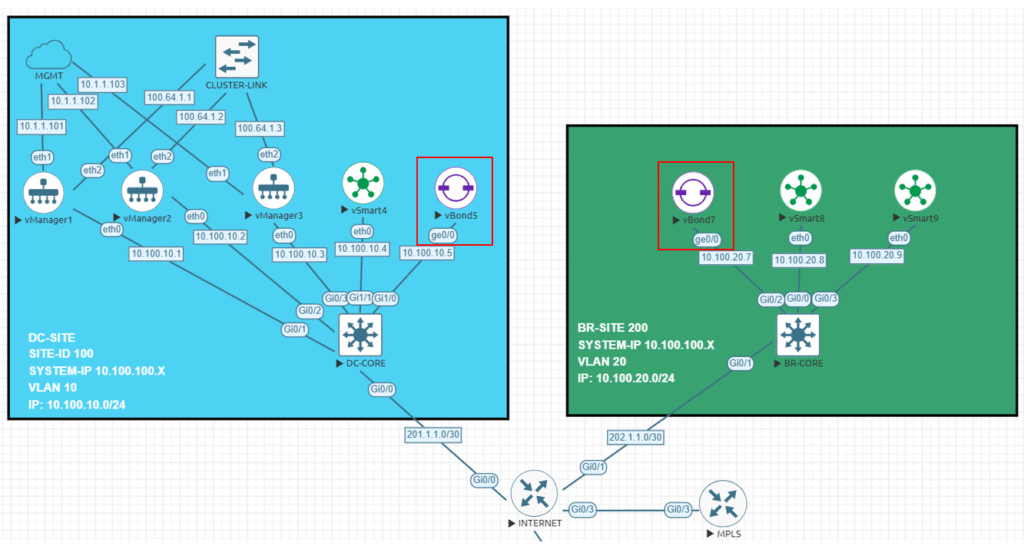
Continuing with the previous post where I installed three Manager in a cluster mode, now I will be deploying two new Orchestrators or vBonds (How most of the people know them), my idea with this second post is to deploy two different Cisco Orchestrators in two different sites, in this case we will have our first vBond named vBond5 hosted in the DC-SITE (Site ID 100), and we will have a new second device named vBond7 in the BR-SITE (site ID 200).
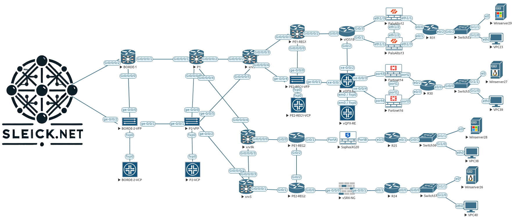
By deploying the two vBond devices in separate locations, we will have s some sort of geo-redundancy HA setup, in red you will find where are located physically these two devices in my topology.
Probably this one will be the easiest due the fact that vBond does not establish any kind of connections between each other, instead they work alone providing the controllers information to the devices who want to join to the SD-WAN network. I have to mention that the key point here is our DNS, our DNS will provide the FQDN name/IP resolution used to reach our vBonds spread across the Internet, in fact Cisco recommends configure all your devices to use the vBond FQDN name instead of the IP address, that will allow you to grow up with more devices without touching your entire network if you add a new vBond.
Step 1 – Configurations
One of the main differences between the vBond and the rest of the controllers is the vBond is just a regular vEdge image, I am not sure if you can use a regular Catalyst image as vBond (probably yes if I am running with some extra minutes, I will test it).
vedge# show version
20.9.5.1
vedge#
Below you will find the devices configuration that I will be using:
vbond5
system
 host-name               vbond5
 system-ip               10.100.100.5
 site-id                 100
 admin-tech-on-failure
 no route-consistency-check
 no vrrp-advt-with-phymac
 sp-organization-name    sleick
 organization-name       sleick
 vbond 10.100.10.5 local
!
vpn 0
 interface ge0/0
  ip address 10.100.10.5/24
  ipv6 dhcp-client
  tunnel-interface
   encapsulation ipsec
   allow-service all
   no allow-service bgp
   allow-service dhcp
   allow-service dns
   allow-service icmp
   no allow-service sshd
   allow-service netconf
   no allow-service ntp
   no allow-service ospf
   no allow-service stun
   allow-service https
  !
  no shutdown
 !
 ip route 0.0.0.0/0 10.100.10.254
!
vbond7
system
 host-name               vBond7
 system-ip               10.100.100.7
 site-id                 200
 admin-tech-on-failure
 no route-consistency-check
 no vrrp-advt-with-phymac
 sp-organization-name    sleick
 organization-name       sleick
 vbond 10.100.20.7 local
!
vpn 0
 interface ge0/0
  ip address 10.100.20.7/24
  ipv6 dhcp-client
  tunnel-interface
   encapsulation ipsec
   allow-service all
   no allow-service bgp
   allow-service dhcp
   allow-service dns
   allow-service icmp
   no allow-service sshd
   allow-service netconf
   no allow-service ntp
   no allow-service ospf
   no allow-service stun
   allow-service https
  !
  no shutdown
 !
 ip route 0.0.0.0/0 10.100.20.254
Step 2 – Add them to the Manager
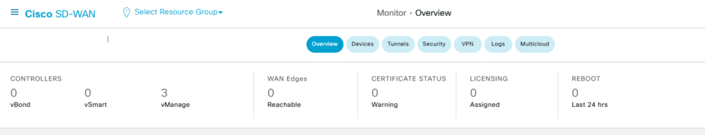
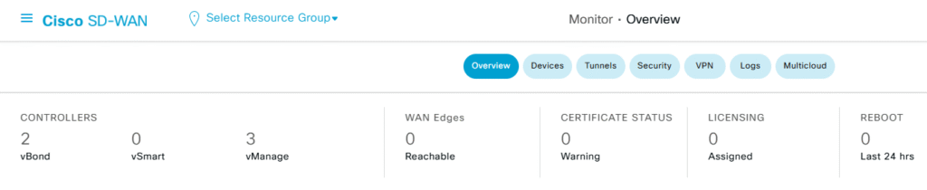
In my previous post I setup three Manager who are working in cluster mode and now is time to add my two vbond to this environment:
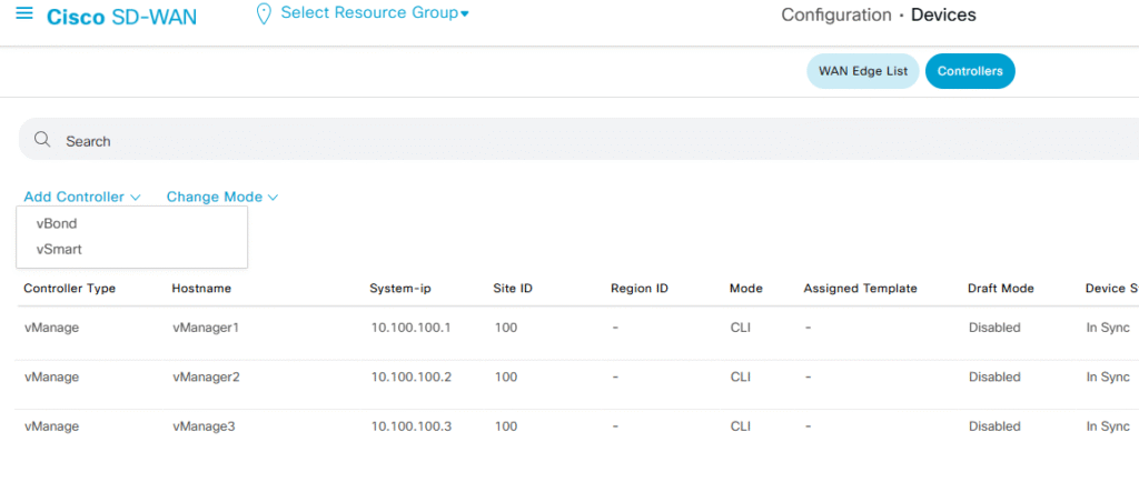
In order to add these two new devices, we just need to go to the Configuration > Devices > Controllers tab, then select the Add Controller using the drop-down menu and select the vBond option
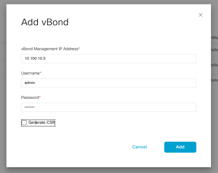
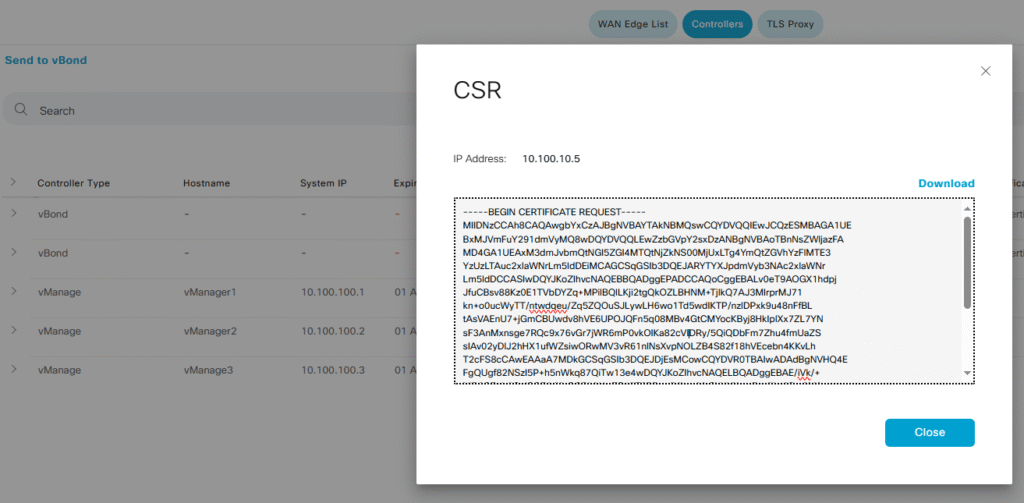
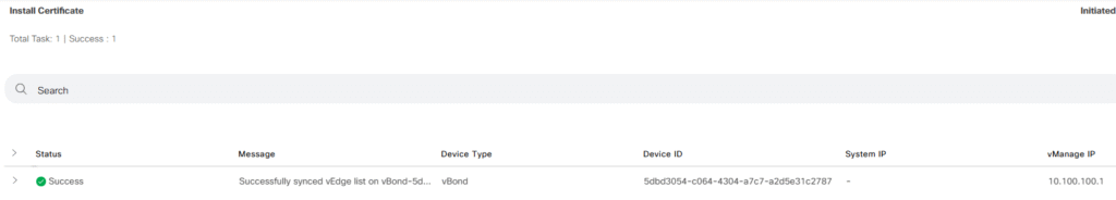
After adding both vBonds we should have both devices under our Manager devices, but we need to generate the CSR certificate, sign it and then install them into the Manager (we only need to do it in one Manager since all of them are sync)
After import the resulting CRT file into my Manager I noticed that I forget to enable Netconf (I added that detail to the previous snipped code above).
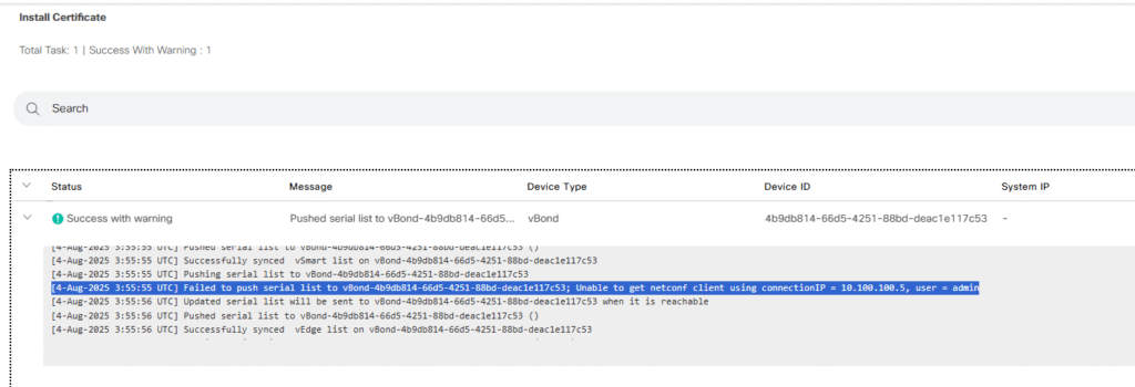
After enable allow-service netconf into the VPN 0 Ge0/0 interface configurations, my Manager is able to add and establish DTLS connections with the vBond
Now I will repeat the previous steps with the second device and then we will check how all the connections look like, this time, I previously enabled netconf and everything went well
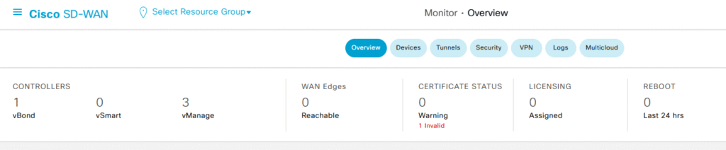
Step 3 – Verifications
With all three managers and two new vBonds up and running in our environment, is time to see what is happening behind the scenes, first of all I will take a look at the two new vBonds. Something important that I need to mention is if you use normal show control connections under the vBond CLI, nothing will be displayed, we need to add the key word orchestrator to our show commands
vbond5# show control connections

! Empty
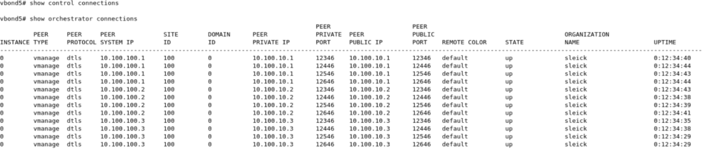
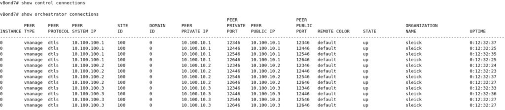
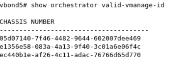
As you can see above, our vBond have four connections with each Manager in my environment, each DTLS connection made against each existing CPU on my Managers, since all of them have four CPU we will have four connections to each one. We can also see the existing valid Manager recorded on each vBonds

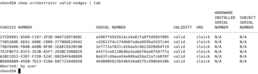
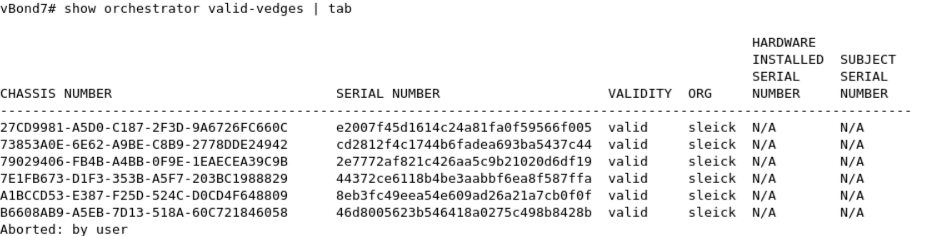
Both vBond devices have all the information about our environment, for example the cEdge list.
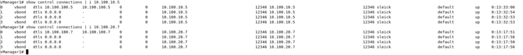
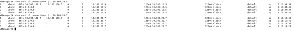
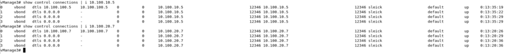
On the other hand, on each Manager we have four connections as well.
As I said at the beginning of this post, the key point here is here is the DNS server, this one will resolve in a round robin fashion (I guess this can be modified) the FQDN name/IP used by our vbond normally spread across our environment, as a best practice our vbonds should be using an static public IP or at least have full cone NAT configuration in order to accept the incoming connections from the different devices. On my next post I will be adding the Controllers to my SD-WAN managers, and then at least one cEdge, during that process we will be able to see with more details how these two vBonds works together orchestrating all our network connections.